Do you understand all the drawings of mechanical parts?
2021.05.06

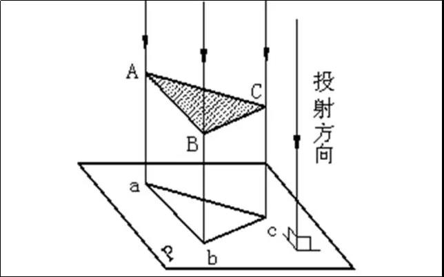
Orthographic projection method
The parallel projection method in which the projection lines are parallel to each other during projection, and the projection line is perpendicular to the projection surface.
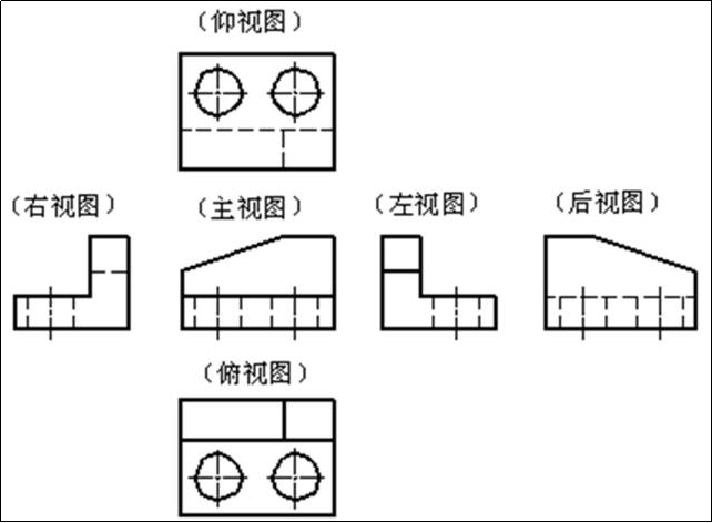
1. Basic View
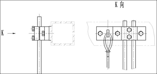
2. To view
3. Partial view
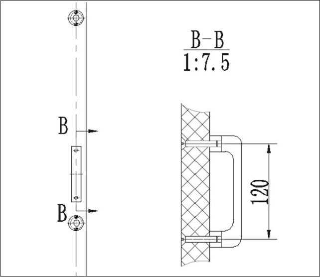
4. Oblique view
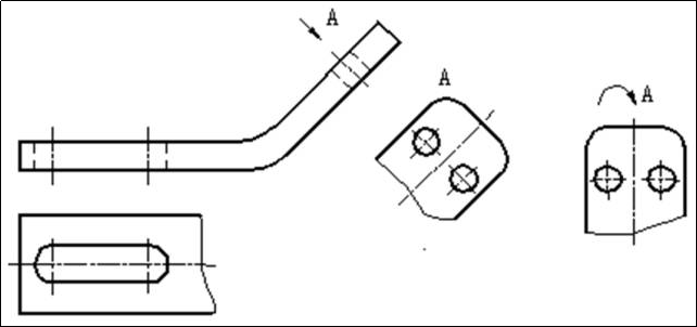
5. Sectional view
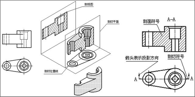
1) Full section view
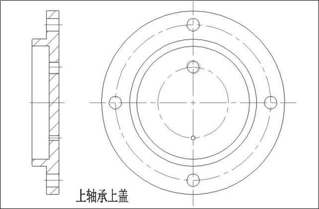
2) Half section view
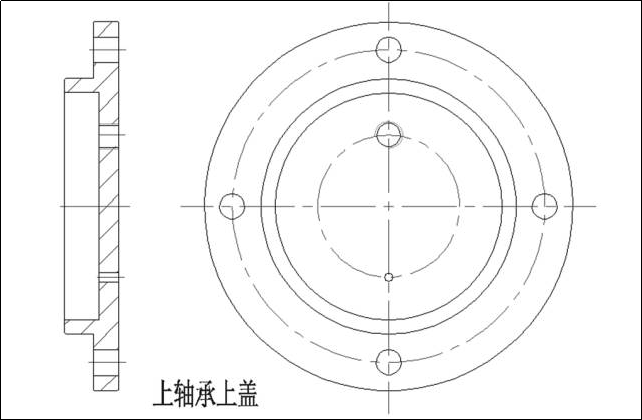
3) Partial cross-sectional view

4) Ladder section
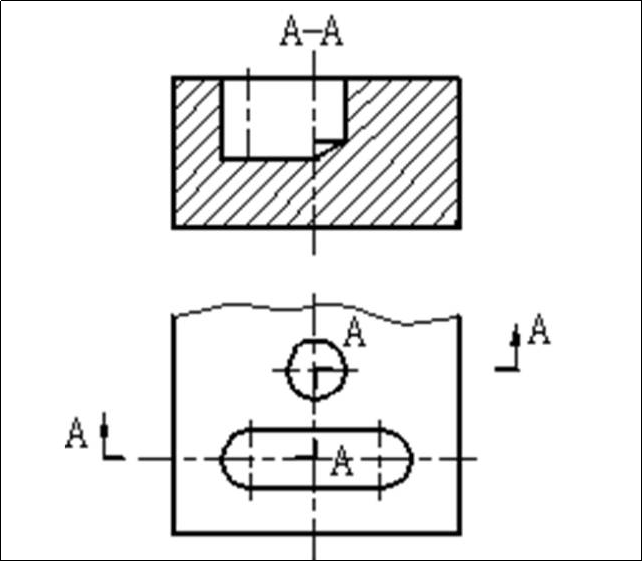
5) Rotating section
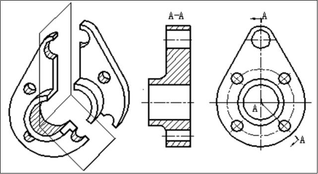
6. Sectional view
Imagine using a cutting plane to cut the machine at a certain place, and only draw the projection of the cut surface shape and draw the figure with the specified cross-sectional symbol, which is called a cross-sectional view, which is referred to as a cross-section for short.
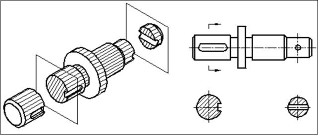
General methods and steps to read parts drawings
1) First look at the title bar to get an overview of the parts
Look at the title bar to understand the name, material, and proportion of the part, so as to get a general understanding of the function of the part, and judge which type of part the part belongs to from the name. Judge the rough processing method of the part from the material. Judge the actual size of the part from the scale, so as to have a preliminary understanding of the part.
2) Analyze the research view and imagine the structure shape
Look at the view, analyze the configuration of each view of the part and the relationship between the views, the expression method and the content of the expression used, and use the combined reading method, the shape analysis method and the line surface analysis method to understand the structure of each part of the part. Imagine the shape, relative position and function of each part of the part.
3) Analyze all sizes and figure out the size requirements
Analyze the view and shape comprehensively, analyze the dimension benchmarks in the three directions of length, width, and height of the part, and then start from the benchmark, take the structural shape analysis as a clue, and then understand the shape and positioning dimensions of each shape, and clarify the role of each size. And size expresses the shape and size of the part. When reading the drawing, the view, size and shape structure should be combined for analysis.
4) Analyze technical requirements and understand the whole picture comprehensively
When reading the drawings, the technical requirements such as surface roughness, dimensional tolerances, shape and position tolerances should be clarified. Understand the meaning of its code names. If necessary, contact the parts related to the part to analyze together.
Next:What guarantees the machining accuracy of machine tools? Understand in seconds after reading it!
Related Information
- Industry news
- The tap or drill bit breaks in the hole, how to fix it?
- Why do airplanes use rivets instead of welding?
- Why are engineering drawings all blueprints?
- How is a ping pong ball made? It turns out that it is made of two pieces of plas
- What to do if quality is abnormal? Doing these 3 things well is the key!
- Weekly News 9.7-9.13
- Huawei's three-fold screen is approaching, and the domestic supply chain is wait
- Innovative application of digital twin technology in integrated die-casting prod
- 5 types of carbide cutting tools, what are the differences? Save this article an
- Global manufacturing PMI in June was 49.5% | Weekly News 7.6-7.12
- Raw material defects | Machining special operations and practical cases 109
- No wonder Toyota stamping is so good: a day in the life of a Toyota stamping sho
- Analysis on the development trend and demand of China's mold industry
- How many types of sealing rings are there in machinery? What are they used for?
- Hangfa, Hangfa, a scar on the hearts of machine processing workers
- How to mill a large arc surface with a small cutter?
- Dynamics of the processing center of the process! What is the fundamental reason
- 500 ° C ultra -strong aluminum alloy! This problem is overcome
- How much do you know about the hometown of machine tools and molds, how much do

 BACK
BACK MT HOME
 Navbar