ONE. Projection principle and three views
1. Basic knowledge of projection
1) Center projection: The light source is emitted from the projection center.
2) Orthographic projection: When the projection rays are parallel to each other and perpendicular to the projection surface, the projection of the object on the projection surface is called orthographic projection.
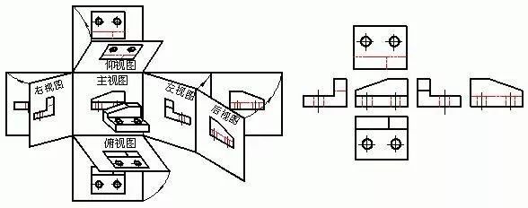
2. Three Views
The view composed of the three main projections of the object, which can correctly reflect the length, width, and height of the object. The orthographic engineering drawing (the main view, the top view, and the three basic views of the left view) are three views, which is a kind of antithesis in the engineering world. A conventional abstract expression of the geometric shape of an object.
1) Main view
To choose the direction that reflects the most obvious features of the object as the projection direction of the main view.
2) Top view

3) Left view

4) Expand the projection surface to summarize
The projection rule is:
a. Main, top view: long alignment
b. Main and left view: high flush
c. Top view and left view: equal width
A simple summary is: the length is aligned, the height is flush, and the width is equal.
5) Projection properties of planes and lines on objects
a. Inclination with the projection plane - shrinkage
b. Perpendicular to the projection plane—accumulation
c. Parallel to the projection plane - authenticity
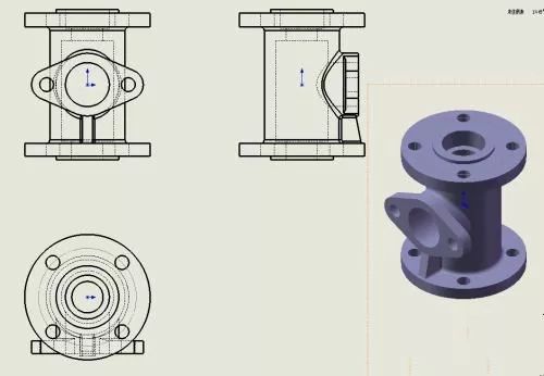
TWO. Various expressions of parts
There are several ways to express the shape of a part:
1. Basic view
Basic views include front view, top view, left view, right view, bottom view, and rear view.
The basic view is placed on a drawing. If it is placed according to the expanded position of the basic view, the name of each view shall not be marked. Otherwise, the view name "X direction" shall be marked above the view, and the corresponding view shall be named with an arrow. Projection direction, and note the same letter.
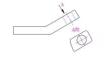
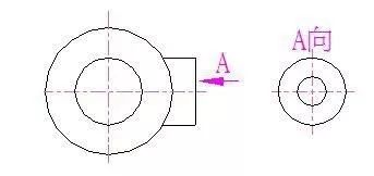
2. Oblique view
When the surface of the part is inclined to the projection surface, the view obtained by adding an auxiliary projection surface parallel to the surface of the part and projecting it is called an oblique view.
3. Partial view
The view obtained by projecting a part of the part to the basic projection surface is called a partial view.
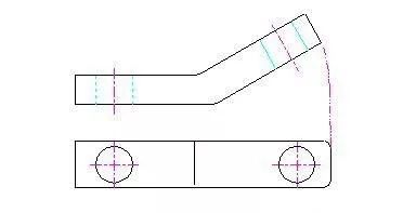
4. Rotate the view
When the inclined part of the part has an obvious rotation axis, it can be imagined that the inclined part is rotated to be parallel to a selected basic projection plane and then projected to the projection plane.
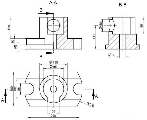
5. Sectional view
The internal structure of the part is complex, and the dotted lines in the view will also increase, which is not good for viewing the picture. It is imaginary to cut the part with a section plane, and then the section is removed and projected.
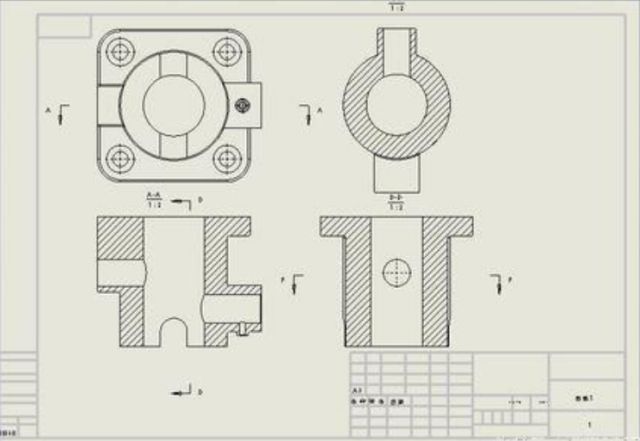
1) Half-section view: used to express the shape and internal structure of an object with a symmetrical plane (delimited by a line of symmetry)
2) Partial section view: used to express the local internal shape of the object and retain most of the shape of the object (partial section)
3) Step sectioning: several parallel section planes are used for stepped sectioning
6. Coincident Sections
The cross-sectional shape used to express the local structure of an object.
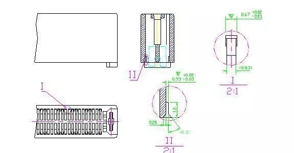
7. Partial enlargement
THREE. The basic steps of drawing
1. Determine the drawing size and drawing scale (product size and structure);
2. Make the frame according to the specified size requirements;
3. View planning: According to the product size and structural complexity, plan the distribution of views, especially the number and distribution of cross-sectional views, the location of technical requirements, and leave space for the title bar;
4. Product analysis and drawing;
5. Dimensions.