Keyword: CNC machining parts Auto Spare Parts Milling machining Turning parts Grinding machining
Contact person: Nick Lee
Phone: (86) 15362887736
E-mail: sales03@dgmtwj.cn
Tel: (86) 769-88388276
Factory: No.2, Baidai Industrial Park, Daojiao Town, Dongguan, China ,
1. Anti-loose double nut

Double helix is used to prevent loosening, it is forbidden to use the structure shown in figure (a), and the structure shown in figure (b) should be used, with flat nuts on the bottom and thick nuts on the top. Two thick nut structures can be used, as shown in Figure (c).
The two nuts are tightened to the top, so that the bolt is pulled in the screwing section and the nut is compressed, which constitutes the longitudinal compression of the threaded connection pair. Installation method: first tighten the lower nut with 80% of the specified tightening torque, and then tighten the upper nut with 100% of the tightening torque; the thread of the lower nut is only subject to the top force, and its height can be reduced, generally use a thin nut ; And the upper nut uses I-type standard nut; some use two equal-height nuts (I-type) in order to prevent wrong installation and ensure that the lower nut has sufficient strength. The structure is simple, the anti-loosening effect is good, the cost is low, and the quality is large, and it is mostly used in the occasions of low-speed heavy load or stable load.
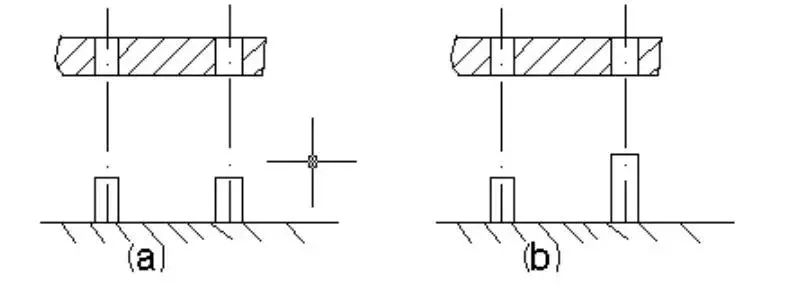
2. The two positioning pins should have different lengths

The assembly of a large box often requires several positioning pins. It is forbidden to make all positioning pins the same height, as shown in Figure a, because it is difficult to align several positioning pins at the same time to close the box. Make different lengths, as shown in Figure b, when closing the box, it is easier to align a positioning pin first.
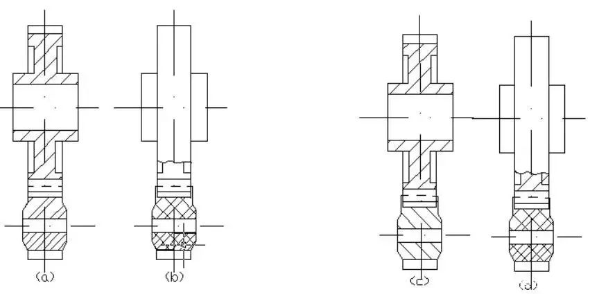
3. In gear transmission, the correct configuration of large and small gears

In order to facilitate installation and avoid step wear during the running process of the gear, in general, the width of the pinion should be 5~10mm wider than that of the large gear, as shown in Figure c, but if the pinion is made of plastic, the pinion should be made of plastic. The tooth width of the gear should be smaller than the tooth width of the large gear, as shown in Figure d, so as to avoid grinding dents on the gear.
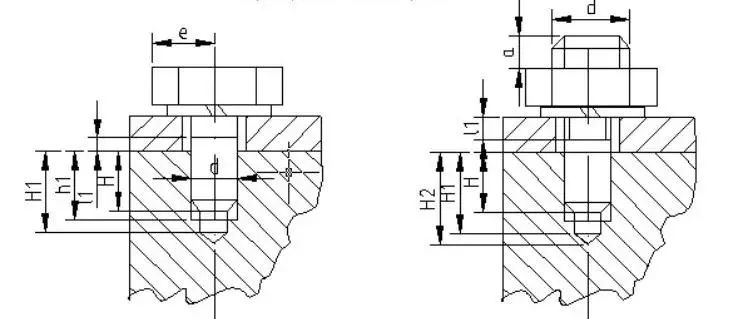
4. Screw connections that are often disassembled and assembled

The screw connection is shown in Figure a. The characteristic of this connection is that the screw is directly screwed into the threaded hole to be connected, without nut, and the structure is relatively simple and compact. In the case of large force or frequent disassembly and assembly, if it is disassembled and assembled frequently, it is easy to wear the thread, which may lead to the scrapping of the connected parts. If it is to be disassembled and assembled frequently, it can be connected by stud bolts, as shown in Figure b, the screwing depth is H , when the screw hole is steel or surface steel, H≈d; when the screw hole is cast iron, H=(1.25~1.5)d, when the screw hole is aluminum alloy, H=(1.5~2.5)d, the thread Hole H1=H+(2~2.5)p (p is thread pitch), drilling depth H2=H1+(0.5~1)d.
5. Intermediate bearing of high-speed shaft

When installing the coupling on the shaft end suspension with high belt rotation, the structure shown in Figure a is prohibited, and the length of the cantilever should be reduced. The larger the cantilever, the greater the deformation and unbalanced weight. Therefore, install the coupling on the cantilever end. In addition to reducing the weight of the coupling, it should also be measured close to the bearing.
6. Small diameter deep hole processing

It is difficult to process deep holes with small diameters, with high cost and low efficiency. It is forbidden to design deep and small diameter lubrication holes on the rotating shaft, as shown in Figure a. If possible, open larger holes as much as possible. , it should be made of different diameters as shown in Figure b.