In order to ensure that the machine or components can be assembled smoothly, and meet the performance requirements specified by the design, and the disassembly and assembly are convenient, the assembly structure between the parts must be made to meet the assembly process requirements. Therefore, when designing and drawing assembly drawings, reasonable assembly structure process issues should be considered.
1. The number of contact surfaces
1. The number of contact surfaces Two parts can only have a pair of contact surfaces in the same direction (horizontal, vertical or radial). This can ensure good contact and reduce the processing requirements, otherwise it will cause processing difficulties and no Will be in contact at the same time. As shown in Figure 1, we must make a> a
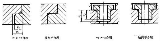
Figure 1 How to draw the contact surface
2. The matching of the journal and the hole is shown in Figure 2. In order to guarantee the matching formed by the deposit φA, φB and φC should no longer form a matching relationship, that is, φB>φC must be maintained.
3. The fit of the cone surface. Because the fit of the cone surface can determine the axial and radial positions at the same time, there must be a gap between the top of the cone and the bottom of the cone when the cone hole is blocked. As shown in Figure 2, L2>L1 must be maintained, otherwise a stable fit will not be obtained. The standard values of the taper and angle of the cone.
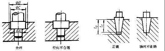
Figure 2 The fit of the journal and the hole and the fit of the tapered surface
4. The contact surfaces of the structural parts at the turning point in two directions should be chamfered, rounded or grooved at the turning point to ensure that the contact surfaces in both directions are in good contact. The turning points should not all be processed into right angles or rounded corners of the same size, because this will cause interference at the turning points during assembly, resulting in poor contact and affecting assembly accuracy. As shown in Figure 3.
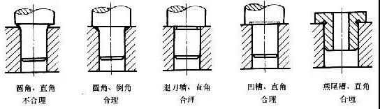
Figure 3 The structure of the turning point of the contact surface
2. The reasonable structure of the threaded connection
In order to ensure that the thread is tight, an undercut groove should be left at the end of the thread or a pit or chamfer should be machined at the end of the screw hole, as shown in Figure 4. In order to ensure good contact between the connecting piece and the connected piece, a counterbore or boss should be formed on the connected piece, as shown in Figure 4. The diameter of the through hole of the connected part should be larger than the major diameter of the thread or the diameter of the screw to facilitate assembly.
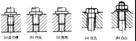
Figure 4 Structure using screw thread
3. Reasonable structure for the axial fixation of the rolling bearing
In order to prevent the axial movement of the rolling bearing, a certain structure must be used to fix the same ring and seat ring. Commonly used axial fixing structure forms are: shaft shoulder, shoulder, elastic retaining ring, straight flange, round nut and non-return washer, and shaft end retaining ring, as shown in Figure 5. The standard size of circlips for holes and shafts can be obtained from the standard. In order to make the rolling bearing rotate flexibly and prevent it from being stuck after thermal expansion, a small amount of axial clearance (usually 0.2-0.3mm) should be left. Common adjustment methods include: replacing metal gaskets of different thicknesses or using screw thrust plates, etc. .
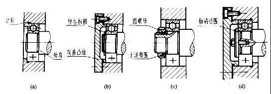
Figure 5 The structure of the rolling bearing ring
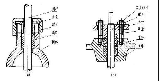
4. Leak-proof structure
The normal operation of machines or components depends to a large extent on the reliability of the seal or leak-proof structure. For this reason, where the rotating shaft and sliding rod (valve rod, piston rod, etc.) of the machine or component extend out of the box (or valve body), it is often made into a stuffing box (cover), filled with special soft quality Packing, press the packing with gland or nut to make the packing stick to the shaft (rod) with proper pressure, so as not to hinder the movement of the shaft (rod), but also prevent the working medium (fluid or gas) from moving along the shaft (rod). ) Leakage, so as to play a role of sealing and preventing leakage, as shown in Figure 6. When drawing the picture, the gland is drawn at the position where the packing has just been filled and the packing has begun to be tightened.