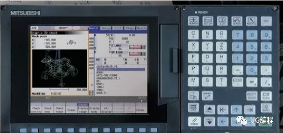
After the hardware connection check and setting of Mitsubishi CNC are completed and power is sent to the system, the green READY light on the display is still off. Moreover, a lot of alarm contents are displayed on the [Diagnosis]-[Alarm] screen, which confuses the commissioning engineers who use Mitsubishi CNC for the first time.
And there are more than 700 kinds of parameters of Mitsubishi CNC, which ones must be set when starting up? How to remove the fault alarm?
This article makes an explanation on the above-mentioned problems based on debugging experience, hoping to be helpful to debugging engineers.
1. Boot parameters
1.1 Setting of basic parameters
After the original system is turned on, the display is in Japanese. For the convenience of operation, first set the parameter #1043=22 (Simplified Chinese). (Some systems such as C64 does not have a simplified Chinese specification, set #1043 = 15 traditional Chinese).
Set #1138=1 (select parameters with the parameter number), that is, after inputting the parameter number, the screen will immediately switch to the parameter screen.
The following are the parameters that must be set after booting:
#1001――Set whether it is a single system or a dual system and the presence or absence of PLC axis.
#1002――Set the number of NC axis and PLC axis.
#1013――Set the name of each axis.
#1037――G code system and compensation type
(Milling machine: #1037=2, lathe #1037=3)
(This parameter must be set before executing #1060 formatting)
#1060 ――This parameter is particularly important. Its function is to "execute system startup initialization"
There are two functions: One is to initialize the parameters according to the set value of #1001——-#1043. The meaning is that the number of NC axes and spindles have been set in #1001——-#1043. After setting #1060, the parameters of each servo axis and spindle are automatically displayed on the screen. Otherwise, the parameters of each servo axis and spindle will not be called.
The second is to format the machining program and tool compensation data. Instead, enter the standard canned cycle.
After setting #1001——-#1043 parameters accurately, you must set #1060 according to the prompts. #1155=100 #1156=100
The fixed signal addresses specified by the Mitsubishi NC system are as follows:
1 axis origin X18 1 axis + limit X28 1 axis-limit X20
2 axis origin X19 2 axis + limit X29 2 axis-limit X21
3-axis origin X1A 3-axis + limit X2A 3-axis-limit X22
4-axis origin X1B 4-axis + limit X2B 4-axis-limit X23
If the input signal address occupied by the origin switch and limit switch is different from the system stipulation, it must be changed by setting parameters
#2073――Set the origin signal address
#2074――Set the positive limit signal address
#2075――Set negative limit signal address
#1226的BIT5=1 (make the above setting effective)
1.2 Servo motor parameter setting:
#2219――(Position encoder resolution)
#2220=――(Speed encoder resolution)
#2225=―――(motor model)
#2236――(Model of connected regenerative braking resistor or power supply unit)
1.3 Parameters related to the spindle
When the system is equipped with a spindle, the following parameters must be set:
#1039――(The setting system has several spindles);
#3024――(Set the connected spindle type
#3024=1. The bus connection is the servo spindle)
#3024=2 Analog output is frequency conversion spindle)
#3237=0004 (PLG is valid)
#3238=0004 #3025=2 (Encoder feedback serial communication is valid. Display the actual speed of the spindle)
#3239――Spindle servo drive type
#3240――Spindle motor type
#3241――The type of braking unit or braking resistor connected
1.4 PLC parameters
#6449=00000011――Counter in the PLC program, the timer is effective.
#6450=00000101――Alarm information and operation information are effective.
#6451=00110000――PLC program communication is valid.
There are as many as 700 parameters of Mitsubishi NC, and it is not necessary and impossible to set all of them when starting up, and the above parameters must be set after starting up.
2. Common fault alarms and troubleshooting after starting up
After power on, many fault alarms may be displayed on the [Diagnosis]-[Alarm] screen, and some alarm debugging is different from the actual phenomenon, and analysis and judgment are needed to remove it.
2.1 [M01 0006 XYZ]――This fault alarm indicates that a certain axis or all three axes exceed the hard limit.
Phenomenon: The actual situation is that each axis has not moved yet and has not touched the limit switch.
Failure analysis and elimination:
A. The signal address of each limit switch is connected in accordance with the system regulations, but connected to a normally open point, so the system has detected an over-travel fault.
Disposal: Just connect the limit switch to a normally closed point, and the fault will be eliminated.
B. The signal address of each limit switch is not connected according to the system regulations.
Disposal: Set parameters #2073, #2074, #2075, #1226, and connect the limit switch signal to a normally closed point.
2.2
[S02 2219 XYZ],
[S02 2220 XYZ],
[S02 2225 XYZ],
[S02 2236 XYZ]――The initial parameter setting is wrong.
Disposal: This means that the servo parameters set after power-on are incorrect, and should be set according to the motor or encoder model.
2.3 [Y03 MCP XYZ]――Servo drive is not installed
Phenomenon: The actual situation is that the servo drive has been installed. Why does this type of alarm occur?
Analysis and disposal:
1. The connecting cables are not plugged in tightly. Unplug the cables and plug them in tightly again.
2. One of the cables is faulty, replace the cable.
3. The power-on sequence is incorrect. The servo system should be powered on first, and then the controller should be powered on last.
4. The axis number of the drive is set correctly. Or the terminal plug is not connected.
2.4 [Z55-RI/O not connected]
Phenomenon: The actual situation is that the system is not equipped with RI/O at all. The other situation is that the system is indeed equipped with RI/O and the connection is completed. But why does this alarm still appear?
analysis:
● The power-on sequence is incorrect. Power on the controller first and then power on the RIO. As a result, the controller cannot detect the RIO.
●. The main cable CF10 (controller-basic I/O) is not connected properly.
Disposal:
1. Change the power-on sequence.
2. Re-plug and tighten the CF10 cable.
3. Check the power supply to RI/O.
2.5 [EMG LINE]――Emergency stop failure caused by improper connection
Analysis: It may be a connection cable failure or a connection failure.
Disposal: re-plug and tighten the cables. Or replace the SH21 cable with R000
cable. Generally, there are 10 wires in the SH21 cable, but for the C1 type drive, the R000 type cable must be used. The R000 cable must be fully connected with 20 wires.
2.6 [EMG SRV]――Emergency stop due to servo system failure
analysis:
1. SH21 cable disconnection may cause this fault. The failure may also occur due to poor connection of the SH21 cable.
2. The fault will also occur if the power-on sequence is not correct.
Disposal: Replace the SH21 cable and power on in the normal order.
2.7 [EMG PLC]――emergency stop caused by PLC program
Remedy: Monitor the Y29F=ON cause in the PLC program, and remove the fault that caused the emergency stop.
2.8 [EMG STOP]――The PLC program is not running.
Disposal:
Check whether the "NCSYS" knob on the back of the controller = 1"
Set the knob to "0"
Set PLC=“RUN” on the display.
After executing "Format PLC Memory" on the communication screen of the GX-D software, re-transfer the PLC program.
2.9[U01——-No User PLC]――The PLC program has not been entered
Disposal: Enter the PLC program.